Here is a rather simple but practical use for digital electronics…..dice! (or in the case a single die)
Unlike many of the kits found online this one does not use a micro controller. The entire circuit is based around 74LSxx logic ICs and a 555 timer for a clock.
How it works:
The 555 timer is the heart of this device, providing the clock pulses each time the button is pressed. With the addition of a transistor, a resistor and capacitor the circuit has been altered from a standard astable clock generator to become a VCO (Voltage Controlled Oscillator). This way, when the button is pressed the die will keep cycling after the release and gradually slow down until the final number is displayed.
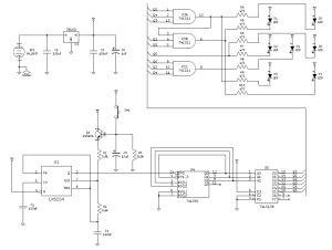
The output of the VCO is then fed into a 74LS90 decade counter (which is configured to only count 0 – 5). The binary output from the 74LS90 is then fed into a 74LS138 (3-8 line decoder) which gives an active LOW output that corresponds to the binary number from the 74LS90. To generate the actual LED patterns for the die display, three 3-input AND gates are used (74LS11). Through negative logic and some clever connections all the LEDs are driven from the outputs of the AND gates or the 3-8 line decoder.
Schematic:
Video:
(Sorry for the poor camera quality)
Photos:
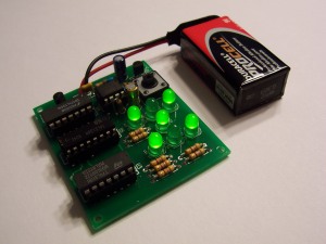
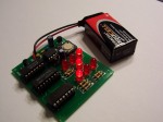
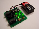
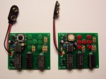
Pingback: Electronics-Lab.com Blog » Blog Archive » 7400 competition entry: Digital die (74XX Family)
sir how to make this?? can you make the instructions?? step by step process.. ???